Assistance systems
VAROS 109 and
VAROS 109 Optic
Basic equipment: 2 assistance systems
The devices VAROS 109 and 109 Optic have helpful assistance systems. These assist you, the local craftsman, in setting up and rating SAT outdoor units. You will be guided through a menu when setting up a SAT system…Starting with the specification of elevation and azimuth up to the automatic evaluation of the measured values. There are 15 orbit positions to choose from.
The second assistant measures the values of an antenna connection box that sits at the end of a distribution. The assistant measures selected transponders. If limit values are not reached, a message appears in the display.
Procedure with the wizard when setting up a SAT outdoor unit:
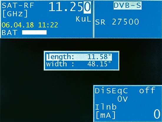
1. Enter the location
The basic requirement for the calculation of elevation and azimuth is the entry of the location. Longitude and latitude are required.
Example Munich: Length: 11.580 / width: 48.130
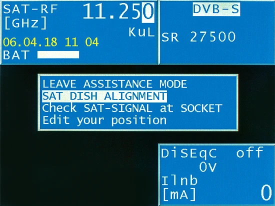
2. Call up the menu
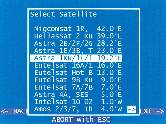
3. Selection of the orbit position
There are 15 orbit positions to choose from (from 42.00 East to 30.00 West).
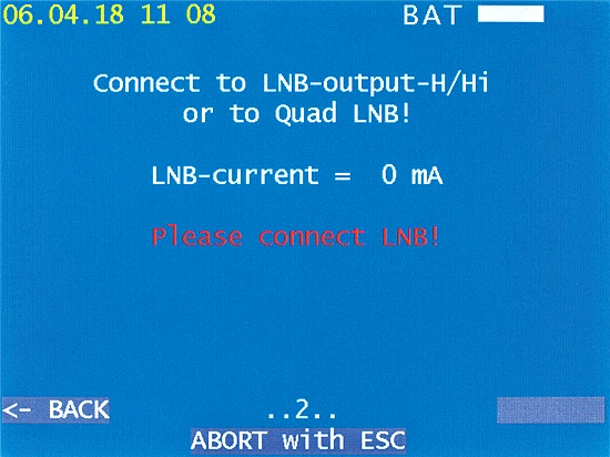
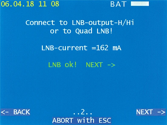
4. Connection of the LNB / current test
First, the output of the LNB is specified. After connecting the device to the receiving head, a current check is performed. Error message occurs at 0 mA and at short circuit.
5. Presetting the SAT mirror
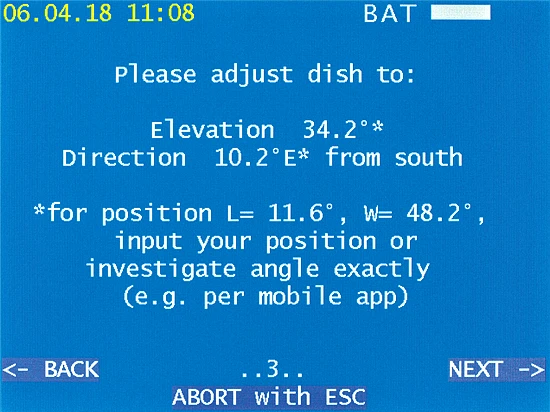
The next step describes the presetting of the SAT outdoor unit. The height angle (elevation) and the orientation (azimuth) are specified. Prerequisite for this information is the correct entry of the location.
6. Setting the SAT mirror
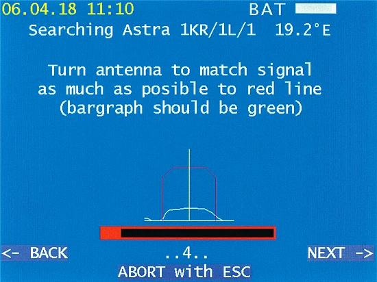
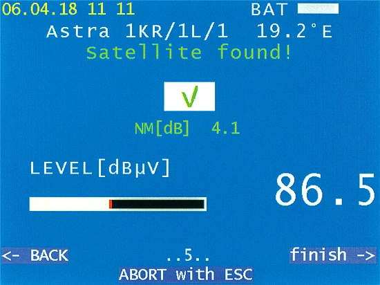
The display shows a virtual transponder (red). A spectrum is detected (white). The bar below the spectrum is switched to red. It must now be a readjustment. The bar must turn green.
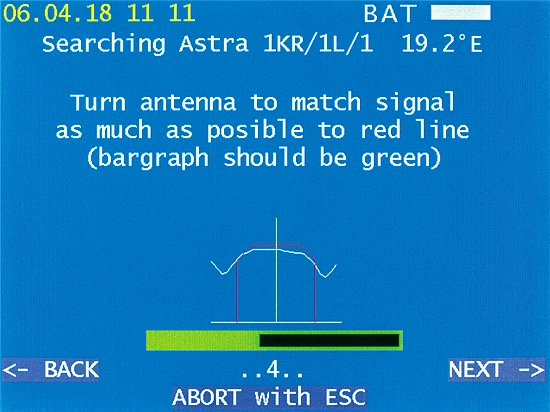
The receiver can lock into the data stream. The bar under the spectrum turns green. The Selected Position was found (here 19,20 East). Now the fine adjustment must be done.
7. Fine adjustment of the SAT mirror / readings
The display shows the position, the level and the system reserve. The technician must now try to set the measured values of the mirror to maximum. The maximum is reached, all values are displayed in green. The receiving unit is optimally aligned.
Procedure with the assistant when checking a SAT socket:
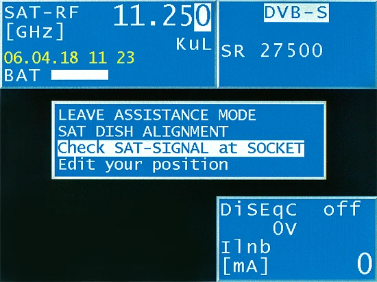
1. Call the menu
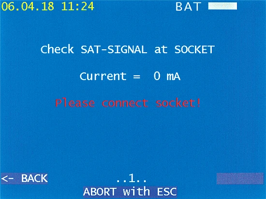
2. Current test on antenna socket
At the beginning, the DC path is checked. Error message at 0 mA and short circuit…Current is 0 mA / open line.
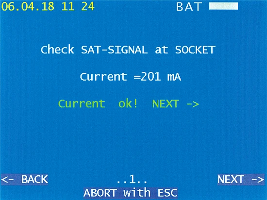
Current is 204 mA / okay
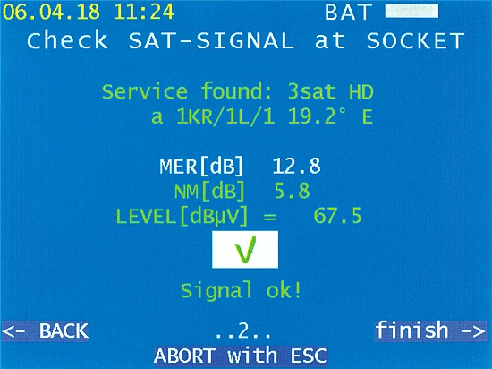
3. Readings: The antenna socket is measured
In picture 1 the level and system reserve are okay. The decrease is positive.
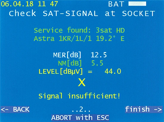
At picture 2 the signal level is too low at 43.5 dBμV. The reserve would be ok. Not all target parameters were reached. Decrease is negative.